For over 60 years, TGH has continued to evolve into one of the most recognized FAA approved (Part 145) instrument repair facilities.
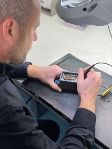 TGH Aviation upholds the highest technical standards, equipped with a professional team of skillful engineers. Our fuel technicians have decades of experience overhauling thousands of fuel flow transmitters for our military, corporate and commercial aviation customers.
TGH Aviation currently operates four precision flow test stands, traceable to NIST, and are capable of calibrating flows of up to 80,000 Pounds per Hour. TGH also holds FAA approved process specifications for the calibration of fuel flow transmitters with rates up to 10,000 Pounds per Minute.
Superior customer service, industry leading expertise and years of experience have made TGH a recognized name in the aviation industry. With value and quality more important than ever, rely on the Experts at TGH Aviation to Keep You Flying!

See here for Pricing or Feel Free to Call us Monday – Fridays, 8:00 am – 4:30 pm at 1 (800) 843-4976. You click here to send us a Request for Quote online through our website.
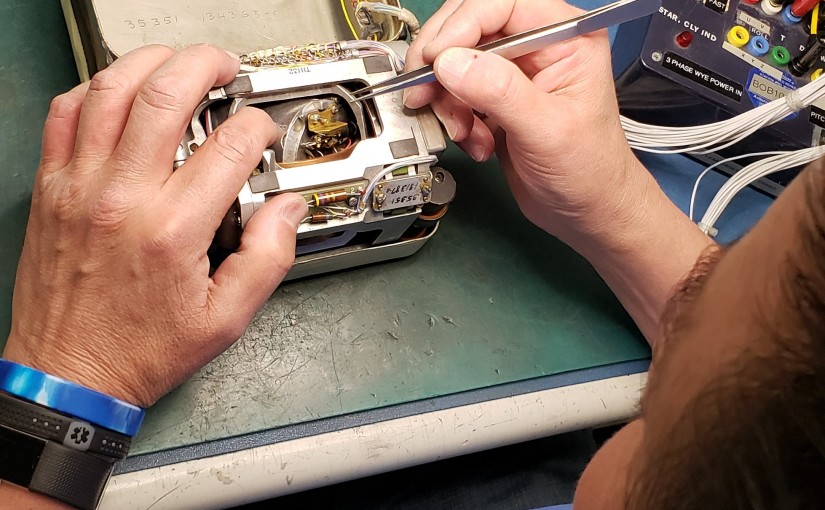
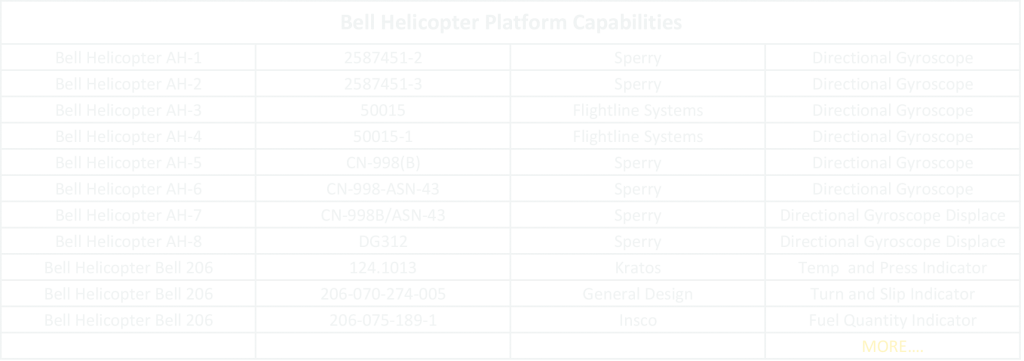
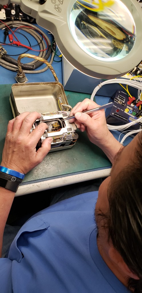
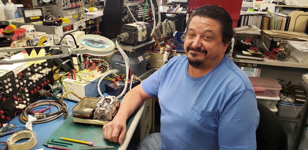
Veteran and Technician Brian Brown started with TGH Aviation in 2005. For the past fourteen years he has been the Repair Lead Tech working on Remote Vertical and Directional Gyros. Brian holds an Degree in Electronics and Served in the Airforce as an Airframe Powerplant Crew Chief. TGH Aviation and its employees enjoy Brian’s sardonic humor and superior overhauls and repairs. His work carries quality and precision. “Life isn’t about our routines; it’s about finding the hidden treasures of splendor in the tiny moments we have” When Brian is not at TGH, he enjoys spending time with his wonderfully large family. With seven children, a beautiful wife, many grandchildren and even a few great grandchildren, he stays busy and happy. His personal hobbies include reading and camping when he’s not taking care of his family. You can be confident in TGH Aviation to be a trusted source for all your Flight Support Systems overhauls and repairs. We employ extraordinary people with great minds and infallible skills. Our dependability is the product of our exceptional team and the mission of TGH Aviation’s FAA Repair Shop. Mario Monti moved to the United States from Italy in 2006 and landed in Placer County, California. As a prior jeweler and watch maker, Mario had great dexterity in working on small intricate motors and devices. He worked as an A & P Mechanic Apprentice at an on-field aircraft repair shop at the Auburn Municipal Airport in 2007. There he became affiliated with TGH Aviation and their instrument repair technicians. Working on aircraft as a mechanic, Mario would often bring instruments to the TGH Repair Shop for repairs and overhauls. The experience in the avionics shop gave Mario a unique view on how flight system components function. When a position opened at TGH in 2009, they were pleased to welcome him aboard. Discovering your destiny can happen in the most of imperceptible of events; staying humble can bring you home. – Corrie Vallance Mario’s expertise brought him quickly up to speed on repairing and overhauling gyros. Ten years later, Mario is one of the main technicians in the repair facility for gyros. In addition to gyros, Mario applies his expertise to repairing and overhauling air-speeds, true air-speeds, pressure altimeters and encoding altimeters. TGH Aviation is appreciative to have great employees like Mario, who came from the other side of the world, to offer their talent to the aviation industry and keep TGH as a trusted source of flight systems support worldwide for over 60 years. TGH Aviation offers aircraft component repair on the following Bell Helicopter Models. Below is a list of the most commonly requested and does not eliminate capabilities on other instruments used in this make of aircraft. If you have an instrument not listed below, please call our Sales Department at 1 (800) 843-4976. Overview of Capacitive Type Fuel Qty. Measuring Systems The Capacitive Type Fuel Qty measuring system utilizes a variable capacitive element in order to vary a precise electrical AC voltage based on the quantity of fuel in the fuel tank. The varying electrical signal, in turn, is used to drive the pointer on a fuel quantity indicator in a manner which is proportional to the amount of fuel in the tank, thereby visibly indicating remaining fuel quantity to the pilot. The typical components in this type of system include the following 1. Signal Conditioner or Control Monitor (If not included in the Stay tuned for upcoming Blogs Typical Failures in Resistive Fuel Quantity Systems Indicator As previously stated the indicator in this type of system is quite simple, typically nothing more than a meter movement mounted within a case. A meter movement consists of a spool of wire mounted on a pivot and jewel housed within a frame. The frame is in fact a large powerful magnet. As electrical current flows through the wire spool it interacts with the magnetic field of the frame causing the spool to rotate on its pivot and jewel. Pivots A pivot is nothing more than a miniature axle. A jewel is a finely ground glass cup within which the ends of the pivot are supported and allowed to rotate. Over time and with constant movement the ends of the pivot will begin to wear down similar to the point on a pencil. Eventually the pivot will become so worn that it can no longer rotate easily. It needs to be sharpened or replaced. Jewels As previously stated, a jewel is nothing more than a finely ground miniature glass cup. Glass is fragile; it breaks very easily when mishandled. The glass also becomes worn from the pivot constantly rotating within it. Eventually the glass will become rough and will need to be re-ground or replaced. Magnets The frame of the meter movement is a large magnet. A magnet is nothing more than a piece of steel within which all of the electrons, sub-atomic particles, have been aligned within a specific pattern. Eventually the electrons move and return to their original locations according to the laws of physics. With the loss of alignment the magnet loses its magnetic power. However while the magnet is still operating properly it, like all magnets, attracts other ferrous metals. The pivot, manufactured with ferrous metal, is in close proximity to the magnet and it is wearing down from rotating within the jewel. As the pivot wears it throws off tiny particles of metal which are attracted to the magnet. Eventually enough of these particles will become lodged between the magnet and wire spool so as to inhibit free movement of the meter. The unit needs to be completely disassembled and thoroughly cleaned. TANK UNITS Resistive Elements As previously described the resistive element is subject to wear from the constant movement of the wiper across its surface. Once it is overly worn or broken it must be replaced. There is no possibility of repair Floats The floats are very often nothing more than hollow metal balls. These sometimes spring leaks. The fuel must be drained and the float must be resealed. Stay tuned for upcoming Blogs Advantages & Disadvantages of Resistive Type Fuel Systems Advantages of Resistive Type Fuel Measurement Systems The primary advantage of this type of system is cost. The components are very simple and therefore very inexpensive to manufacture. A second advantage is reliability. Again these are very simple components involving very few piece parts to manufacture; the fewer parts that are involved then the less that can go wrong. The third and final advantage is that the system, while not optimal, does provide a reasonable amount of accuracy. When utilized on a small aircraft, carrying small quantities of fuel with a limited flight range the accuracy that is provided by this system is adequate. Disadvantages of Resistive Type Fuel Quantity Systems Inaccuracy due to Physics Stay tuned for upcoming Blogs Theory of Operation (Resistive FQM Systems) For the purposes of discussing the operation of the Resistive Fuel Quantity Measurement System, in the paragraph below, the following assumptions are to be made: 1. The aircraft utilizes a 28 Volt DC Power Supply 2. The meter movement within the indicator is the most common type used, which is a 100mv, d’arsonval type. This means that it requires 100mv of electrical current to drive the pointer on the meter movement from zero deflection to full deflection. When power (V+) is applied to one side the resistive element and ground is applied to the other end and the desired maximum electrical current is 100mv, then Ohm’s Law can be applied in order to determine the required value for the resistive element as follows: R = E/I Where R= Resistance, E= Voltage and I = Current. Since the values of E and I are known, 28 Volts DC and 100mv respectively, then R is resolved as follows: 28/.1 = 280 Therefore the value of the resistive element to be used is equal to 280 Ohms at its minimum value, which would equate to a maximum current flow of 100mv. A reasonable design, would dictate that the system would change 1mv for each 1% of fuel used. Using that model then 1mv (1% of the fuel remains) would be our zero point on our indicator. Once again Ohm’s Law dictates the value of our resistive element as follows: 28/.01 = 2800 Ohms Therefore our resistive element must be variable from 280 ohms up to 2,800 Ohms. The operation of the system is now very straight forward, when the fuel tank is empty the float is at its very lowest point and the wiper resistive element follows the float. Therefore the wiper is at the point of the resistor which is closest to ground and furthest from the source of power or 2800 Ohms. This would provide only 1mv of power to the meter movement and only 1% deflection of the pointer or our Zero (EMPTY) setting. When the fuel tank is full the float and wiper both will be at their highest point, closest to the source of power or 280 Ohms. This would provide 100mv of power to our meter movement and 100% deflection of the pointer or our FULL setting. As the voltage is constant and both electrical current and resistance are perfectly linear then our pointer travel will also be perfectly linear. Stay tuned for upcoming Blogs Get to Know the Fuel Quantity Indicator The indicator for a resistive fuel quantity system is typically a very simple instrument consisting mainly of a meter movement housed within a standard 3-1/8” case. On occasion the indicator may have some signal conditioning element within it, however that is quite rare and when it does occur even that will be a very simple voltage divider or a single stage amplifier. The most common meter movement used in these indicators is of the d’arsonval type and which is typically 100 milli-volts full scale. Stay tuned for upcoming Blogs Fuel Measuring Systems- Tank Unit The tank unit is the component which gives the system its name “Resistive Fuel Quantity Measuring System”. The tank unit is comprised of a float which is mechanically linked to a variable resistive element. The float rides on top of the fuel and will move up or down depending on the level of fuel within the tank. The floats movement is coupled via a linkage arm and gear assembly to a variable resistive element which then mimics the movement of the float. The variable resistive element is comprised of two parts; a resistive strip, typically manufactured with Nichrome wire, and a wiper assembly. Nichrome wire has a predictable and stable resistance to electricity per inch of wire. Therefore it is possible to cut and form a piece of nichrome wire to a very exact electrical resistance value simply by adjusting the length of wire. The wiper assembly is a moveable electrical contact which slides across the length of the nichrome wire while making direct physical contact with the wire. In our fuel measuring system one end of the nichrome wire will be connected to the aircraft power source and the other end will be connected to ground. The wiper will tap a varying amount of electricity off of the nichrome due to its physical contact. The amount of electricity that is tapped is determined by the overall resistive value of the wire and precisely where on the wire that the wiper is making physical contact. If the wiper has moved 24% down the length of the wire then 75% of the electricity is tapped off; at 50% movement then 50% is tapped off; at 75% movement then 25% is tapped off. This relationship is very predictable and very consistent and operates precisely under the principles of Ohm’s Law (E=I/R). The electricity that is tapped off by the wiper is then transmitted by wire directly to the Fuel Quantity Indicator and is used to drive the pointer indicating fuel qty. Stay tuned for upcoming BlogsEmployee Appreciation | Meet Brian Brown
Corrie Vallance
Employee Appreciation | Meet Mario Monti


Capabilities on Bell Helicopters
Overview of Capacitive Type Fuel Qty. Measuring Systems
indicator
2. Tank Unit (Fuel Qty Sender, Fuel Probe)
3. Indicator 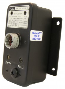
Typical Failures in Resistive Fuel Quantity Systems
Advantages & Disadvantages of Resistive Type Fuel Systems
The fuel, within the aircraft’s tanks, is subject to the laws of physics. Therefore it moves when the aircraft moves. It is affected by gravity and centrifugal force. When the aircraft banks for a turn the fuel slops to one side. When the aircraft climbs the fuel flows to the back of the tank. When the aircraft dives the fuel flows towards the front of the tank. The float is in a fixed position and can only respond to the up and down motion of the fuel. If all of the fuel has moved forward and away from the float then the float will fall down and indicate a lower amount of fuel then is currently available, conversely if the mass of fuel gathers in the area where the float is located then the float indicates a higher amount of fuel then what is actually available. Only when the aircraft is flying straight and level will the system provide an accurate report of fuel quantity. These types of inaccuracies are intolerable on a long range aircraft which is carrying thousands of pounds of fuel.Theory of Operation (Resistive FQM Systems)
Get to Know the Fuel Quantity Indicator
Fuel Measuring Systems- Tank Unit


